The IADC Technology Value Guide is intended to suggest positive aspects of
various types of well-construction technologies, as well as point out potential
drawbacks. In addition, each technology listed (column headers) in the TVG is
linked to separate pages containing definitions, illustrations and training
resources.
IADC encourages its members to provide feedback on the TVG, and to supply
relevant illustrations and training resources. The TVG is an evergreen document,
and IADC are open to contributions. For more information, please email
mike.killalea@iadc.org.
|
|
● |
Yes (has the ability to have this functionality) |
◐ |
Sometimes |
The IADC Technology Value Guide is intended to provide general information
regarding the positive and negative aspects of key well-construction
technologies.
|
|

Figure 1" National Oilwell Varco (NOV) top drive. Courtesy of NOV. |
Top drive systems primarily function like a power swivel, applying rotary torque
to the drill pipe at the top of the drill string. Some early top drives are
suspended below a separate rotary swivel, while some have an integrated swivel.
The prime difference from a power swivel is the power, load rating, and ability
to connect the stand or drill string to the powered main shaft at well center
without human intervention through the use of a "pipe handler" under the top
drive. This facilitates drilling ahead with stands of drillpipe where prior to
this all connections had to be made at the drill floor which meant only one
single from the rathole could be added at a time. Top Drives are an alternative
to Kelly drive systems powered by a rotary table. Top drives also provide
improved back reaming capability to aid in pulling out of the well while
rotating. Top Drives allow both pumping and rotating during hoisting, making it
possible to pull out of a wellbore with mechanical obstructions. Additionally, a
remote kelly cock, or integrated BOP valve, is connected to the top drive main
shaft and can be remotely actuated from the driller's console. Top drives are
generally rated for hoisting loads at 150 ton, 250 ton, 350 ton, 500 ton, 750
ton, 1000 ton, and 1250 ton. A rotary table is occasionally still used for a
back-up rotation system, or as a method to turn casing in the well while adding
a joint of casing to the string to avoid potential sticking problems. In a few
cases no rotary exists and a simple device to handle the slips is put in its
place at well center on the rig floor.
Training (examples):
Aker Solutions
National Oilwell Varco
TTS Sense
|
 Figures
2 & 3: At bottom, Aker Solutionís MH DDM 1000 ACô
top drive. At left, Akerís MH MDDM 1000 ACô top drive. Courtesy of Aker
Solutions.

|
↑
top
|
|
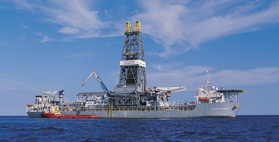
Figure 4: Transocean Discoverer Enterprise. Courtesy of Transocean.
|
The use of machines to facilitate simultaneous activities in a safe manner, such
as offline standbuilding while drilling ahead and running a BOP in deepwater
operations while drilling tophole. The challenge associated with multi-activity
operations usually includes number of operators required as well as safety
systems to manage potential interference between machinery and personnel. |
↑
top
|
|

Figure 5: NOV PS-30 Power Slips. Courtesy of
NOV. |
Slips: Wedge-shaped pieces of metal with serrated inserts (dies) or other
gripping elements, such as serrated buttons, that suspend the drill pipe or
drill collars in the master bushing of the rotary table when it is necessary to
disconnect the drill stem from the kelly or from the top-drive unitís drive
shaft. Rotary slips fit around the drill pipe and wedge against the master
bushing to support the pipe. Drill collar slips fit around a drill collar and
wedge against the master bushing to support the drill collar. Power slips are
pneumatically or hydraulically actuated devices that allow the crew to dispense
with the manual handling of slips when making a connection. |
↑
top
|
|

Figure 6: NOV BX-4-75 Power Elevator. Courtesy
of NOV. |
These are air or hydraulic elevators operated on bails hanging below the
traveling equipment, which provide a remote opening and closing of the elevator
without human intervention. |
↑
top
|
|

Figure 7: Canrig mechanized roughneck. Courtesy
of Canrig. |
A machine that integrates the function of a spinning wrench and a torque wrench
to make up and break out drill pipe connections. These machines evolved to
replace manual connections and increase the safety of making and breaking
connections by eliminating the manual handling involved with suspended
individual tools. The machine may be configured as a single wire hung device or
as an arm-deployed or floor rail-mounted device to facilitate the continual
hydraulic movement of the machine in and out from a well center, mousehole, and
in some cases the rathole location. Some larger machines incorporate pipe thread
doping and cleaning systems, bit breakers, mud buckets and full remote control
and/or automated operations. Some machines adapt to connect casing tong
mechanisms and some cover a full range of tubular and casing up to 20Ē.
Training:
|
|
|
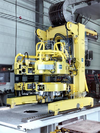
Figure 8: TTS Energy Multifunctional Roughneck. Courtesy of TTS Energy.
|
Functionally replaces the derrickman in guiding pipe from the set-back to the
travelling equipment. Some systems have hoist mechanisms and some work in
conjunction with an intermediate and lower arm. These machines are remote
controlled or operate in semi- or fully-automated mode from a derrick mounted
station/cabin or a floor mounted station/cabin or a driller's station integrated
control system. |
↑
top
A two arm system is the combination of an upper tailing arm and an intermediate
hoisting/racking arm. A three arm system is the combination of a two arm system
and a lower racking arm often added to aid in stability of handling drillpipe on
a floating vessel, and some systems also use the lower racking arm as a riser
tailing device. Each arm (in most cases) is independently controlled in a
separate cabin or control station. Usually the arms are hydraulic systems used
in conjunction with an air or hydraulic-operated latched fingerboard.
Upper Tailing Arm: A heavy duty guide arm used as an upper racking arm to
replace the derrickman's function of manually moving stands of drill pipe from
the fingerboard to the elevators and back. It does not hoist the stand. The
upper tailing arm is usually installed underneath the diving board between the
fingerboards and operated by a man standing on the diving board or standing on
the drill floor. Generally used on land rigs or smaller jack up offshore rigs
where there is no to limited rig motion
Intermediate Racking Arm: Usually the hoisting mechanical device in a two or
three arm pipehandling system connected to the derrick in the middle of the
set-back, guiding the center of a drilling stand between the set back stored
position and the well center. The arm is usually controlled locally or
integrated in an automated or semi-automated system ran from the drill floor or
in the driller's cabin.
Lower Racking Arm: Primarily a guide arm often used as a second or third arm in
a pipehandling system. The arm is usually controlled locally or integrated in an
automated or semi-automated system ran from the drill floor or in the drillerís
cabin.
Lower Tailing Arm: A heavy duty guide arm. Sometimes used as a lower racking arm
but primarily used for the tailing and guiding of the riser on a floating vessel
and as a general heavy lifting crane. Usually on the rig floor or suspended
slightly above the rig floor.
|
|
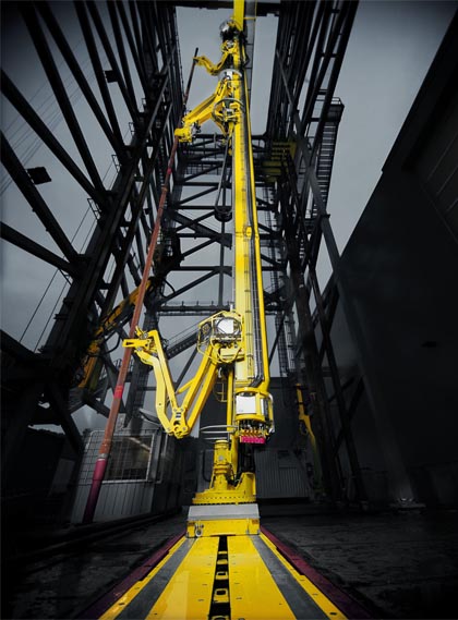
Figure 9: TTS Energy Smart Racker. Courtesy of TTS Energy.
|
An automated system of arms on a column that can be a fixed rotating (radial
pattern) machine or a traveling and rotating machine. Usually consists of a
single guide and single gripping hoist arm and has a primary function of
tripping the pipe without the intervention of human labor. Various modes and
versions exist with additional functionality including additional arms and tools
to facilitate stand-building off-line, riser tailing, riser tripping (stands of
riser), casing tripping (stands of casing) and integrated Iron Roughnecks. Three
fingerboard designs are common, the star fingerboard, where the column is a
fixed rotating design and the arms place the pipe in a radial fashion, the X-Y
fingerboard which mimics the traditional left-hand, right hand fingerboard with
the exception of each stand or a number of stands are locked in place with a
remotely controlled finger latch, or a parallel fingerboard where all the
fingers point towards well center and the racker travels in front of the set
back rotating 180 degrees to present the tubular stand at well center (this
system also latches like the X-Y fingerboard. These systems are prevalent on
high-spec offshore rigs and floating vessels where the lateral stand loads are
too high for typical manual operations by a derrickman.
|
↑
top
In a parallel racking system often the design will include a second racker on
the same track system. This is to facilitate redundancy as well as efficiency of
a rig that can build stands off-line while tripping in or out of the well.
↑
top
A mechanized or automated mud capturing device that also serves as a spray
protection for the crew when pulling a wet string tripping out of the hole.
Typically mounted on the drill floor where it is actuated to well center or on
an Iron Roughneck that brings it to well center during deployment. The captured
mud is returned to the pits, reducing waste and cost.
↑
top
A remote controlled or automated system for cleaning and lubricating the drill
pipe connections while tripping in the hole. Often times connected to an Iron
Roughneck.
↑
top
A process that incorporates machines to facilitate the construction of stands of
drillpipe away from the activities at well center. This may be done vertically
using one or more mousehole. This can also be done horizontally. This is done
independently, or in a parallel process, of normal drilling.
↑
top
|
|

Figure 10: Canrig horizontal to vertical pipe
transfer arm. Courtesy of Canrig. |
Horizontal to Vertical Pipe Transfer Arm: A device designed to transition a
single tubular (and in a few cases whole stands) between a horizontal or angled
presentation and a vertical position in a mousehole or at well center. The
machine is usually integrated in to a V-door.
Pipehandling Boom: An arm-based machine that usually transitions drill pipe from
the horizontal to the vertical position in a single motion. It is usually
rotated around a fixed pivot point in the sub structure and is mostly used in
land rig applications. |

Figure 11: Courtesy of Precision Drilling
Oilfield Services Corp. |
↑
top
A derrick- or mast-fixed arm that is deployed solely for running casing. It
provides stability and control in the running of casing singles.
↑
top
An extending or telescoping arm with attachable heads, used to guide riser to
well center, manipulate tubulars or other items about the drill floor
↑
top
|
|

Figure 12a: NOV CRT-350 Casing Running Tool.
Courtesy of NOV.
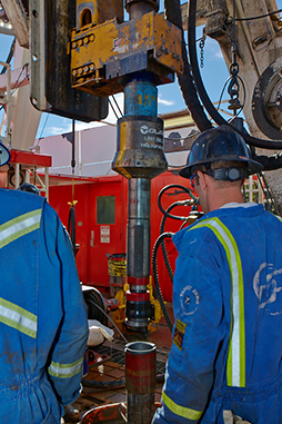
Figure 12b: Photo of Volant Casing Running Tool (internal) CRTi courtesy Volant Products.
|
An adaptor that attaches to the top drive
eliminating floor tongs and manual handling of casing using the power and
rotation from the top drive. When connected to the top of the casing it is used
to spin in and make-up the connection of the casing accurately. This system may
also include a casing fill-up and/or casing circulation function. A floor based
method of holding adequate back up or a slip system is needed to react to the
torque in the string as the top drive is made up to the upper casing joint. |
↑
top
Horizontal Tubular Transfer: A horizontal or angled machine that transfers tubulars from the pipe deck/rack to the rig floor, often achieved with carts,
carriages, rollers, or belts.
Pipe Conveyor: A type of horizontal tubular transfer generally using a
continuous belt to convey the tubulars along the machine. Pipe Conveyors can
utilize only a belt that is loaded directly with a tubular handling crane, while
others also include side loading arms that transfer the pipe between the tubular
handling crane and belt.
Catwalk Machine: A horizontal pipe and/or riser handling system which transports tubulars and/or risers in and out of the rig floor. Typically these machines are
mounted at the drill floor elevation and are loaded with a deck crane or
dedicated tubular handling crane.
↑
top
A tubular handling machine is a pipe deck tubular handling arm, some of which
handle one joint of pipe at a time and some which handle bundles; however, these
are uniquely identified by the ability to handle tubulars on the pipe deck/rack
mechanically to connect to the pipe. These machines typically interface with
Pipe conveyors or pipe catwalk machines.
↑
top
The utility functions associated with a traditional mousehole, such as hoisting,
lowering, rotating, and grabbing or actuating with a slip assembly. Usually
associated with facilitating offline standbuilding activities.
↑
top
|
|
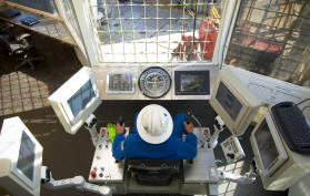
Figure 13: Courtesy of Canrig. |
An enclosure for remotely controlling equipment. Generally (but
not always) used to describe a Driller's cabin. The enclosure typically includes
both controls and instrumentation at an Operator's workstation. These cabins
have included controlled environment features such as heating and/or air
conditioning. Cabins commonly have windows to see operations and may also be
augmented with video displays for cameras showing areas difficult to see
directly. The enclosure may also be purged to maintain a safe level of flammable
gases or vapors by positive pressure or continuous flow. Integrated control
cabins also often have some method of communicating with the rig floor
integrated into the system. Often associated with an integrated control cabin is
a control chair(s) for the driller with additional stations for pipehandling
functions or redundancy. Ergonomics are also considered to help eliminate
operator fatigue. The amount of stations ranges from just the drillerís station
up to five stations on a multi-activity deepwater drillship. |
↑
top
A rig that utilizes a hydraulic powered hoisting system having long stroke
cylinders for pushing a sheave cluster and traveling assembly vertically. These
cylinders and sheave cluster are guided by a guide frame to allow the sheave
cluster to raise and lower the top drive and elevator during drilling
operations. The number of cylinders is determined by the load capacity. The
Cylinder Rig is an alternative system to the conventional drawworks, derrick,
and crown-mounted motion compensation systems. Since the hydraulic cylinders
carry the load, no derrick structure is required. However, the top drive will
need a guiding structure for travel and to absorb Torque.
↑
top
An additional device that can be installed on a passive heave compensator
system, such as a crown-mounted or drill string compensator. It is designed to
improve the performance and accuracy of the passive compensator during critical
sea bed landings and critical weight on bit requirements.
↑
top
|
|

Figure 14: NOV AHD-1250 Active Heave Drawworks.
Courtesy of NOV. |
A drawworks with an advanced controls system and additional power to provide the
heave compensation of the string on a floating vessel instead of the traditional
crown-mounted or drill-string motion compensation systems. Through use of the
reference frame system, the drawworks is activated via the control system
forwards and backwards to move the top drive, string, riser, etc. to maintain a
static position relative to the ocean floor.
Dual Active Heave Drawworks System: utilization of two active heave drawworks to
provide full load compensation without the need of a crown-mounted compensation
system and to increase the speed of the traveling assembly.
|
↑
top
A control arrangement to gradually phase the speed of all the active mud pumps
so that all the pistons are travelling in a synchronized fashion to smooth out
the average flow and pressure pulsations down the drillpipe.
↑
top
A remotely controlled, actuated, and/or reset high pressure mud pump discharge
relief valve. This system may be remotely operated or controlled electronically,
pneumatically, hydraulically or in some other manner.
↑
top
An electronic system for communicating critical control functions from the rig
floor to the BOP stack. The system incorporates two communicating controllers,
one receiving a command from the rig floor and translating that command to the
second controller, which verifies receipt of the command on the BOP stack, and
in turn converts the electrical signal into a hydraulic function. The reason for
using these systems is primarily in deepwater applications in excess of 4000
feet where response speed becomes a critical issue. The traditional methods of
using hydraulics/pneumatics to transfer this signal over long distances are no
longer sufficient. From four to seven thousand feet this is being carried out
with an electrical signal, however beyond 7000 feet, these systems are using
fiber optics to achieve sufficient response times. On some jackups, multiplex
controls are used to eliminate cable runs between the control system in the hull
and the cantilever based BOP stack.
Training:
GE Oil & Gas
↑
top
Signals transmitted in real-time (while drilling) from an instrument located
near the bottom of the drill string to a receiving monitor on the surface (a
surface-readout). Downhole telemetry may be transmitted via mud pulses (much as
sonar signals are transmitted through water), through electro-mechanical methods
(radio transmission) or via a wire within the drillpipe. Frequently, downhole
telemetry is employed in determining the drift angle and direction of a deviated
wellbore. The signal from the downhole tool to the surface is called an uplink.
(See measurement while drilling)
↑
top
|
|

Figure 15: NOV pipedeck operator/standbuilding chair. Courtesy
of NOV. |
|
↑
top
A PLC controlled flow distribution and remote valve controlled system to ensure
even flow distribution to all shakers including a start up procedure when flow
is increasing or a stop procedure when flow is decreasing.
↑
top
A system of a control unit and drilling mud mixing equipment where the drilling
mud mixing process can be automated, either to preset drilling mud properties or
to automatically control and mixing of drilling mud properties while drilling.
For instance, measurements of downhole and surface parameters can be used to
automatically adjust the mud conditions while drilling if well conditions
changes.
↑
top
A system with an automatic dustproof machine able to cut smaller sacks with
powder. It will separate powder into a feeding unit towards the mud mixer and
packaging into a waste material compacting unit. This slitter unit is often
integrated in a mud mixing system with lifting table for pallets and a PLC
controlled system with a local control panel. All this often delivered on a skid
for easy installation into the Mud Mix room/area.
↑
top
|
|
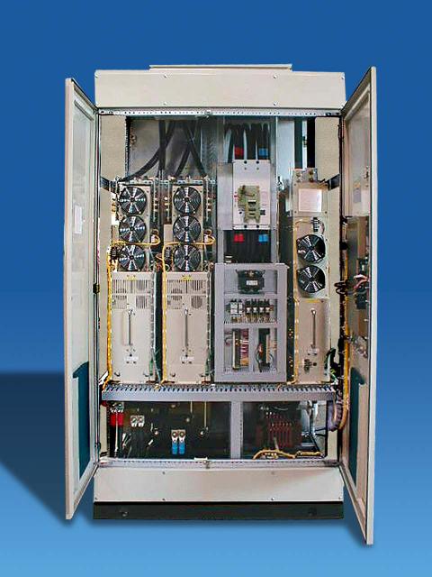
Figure 16: Omron Oilfield and Marine AC Drive (VFD).
Courtesy of Omron. |
An AC Drive is a system for controlling the rotational speed and/or torque of an
alternating current (AC) electric motor by controlling the frequency of the
electrical power supplied to the motor.
Training:
|
↑
top
Automatic Driller: A mechanism used to regulate the amount of weight on the bit
without the continual control by drilling personnel. Automatic drillers free the
driller from the sometimes tedious task of manipulating the drawworks brake to
maintain correct weight on the bit. It may also have the capability to control
weight within safe operating limits when more than one drilling parameter
changes at a time.
Training:
↑
top
|
Canrig
IADC
NOV
PETEX
Precision Drilling
Transocean
TTS Energy
*Other companies/individuals were invited to participate and chose not to.
1. National Oilwell Varco top drive
2 & 3. Aker Solutions
4. Transocean Discoverer Enterprise
5. National Oilwell Varco PS-30 Power Slips
6. National Oilwell Varco BX-4-75 Power Elevator
7. Canrig mechanized roughneck
8. TTS Energy Multifunctional Roughneck
9. TTS Energy Smart Racker
10. Canrig horizontal to vertical pipe transfer arm
11. Precision Drilling Oilfield Services Corp.
12. National Oilwell Varco CRT-350 Casing Running Tool
13. Canrig
14. National Oilwell Varco AHD-1250 Active Heave Drawworks
15. National Oilwell Varco pipedeck operator/standbuilding chair
16. Omron Oilfield and Marine AC Drive (VFD)
|


